With a properly developed WPS and robust QA/QC, SAW welds in duplex stainless steels can deliver
mechanical properties and corrosion performance comparable to, or locally better than, the base material,
making them suitable for long‑life pressure vessel applications.[2][8][1]
2. Duplex Stainless Steels in Pressure Vessel Service
2.1 Grades and typical applications
Duplex stainless steels combine ferritic and austenitic phases in roughly equal proportions, providing higher
yield strength and superior resistance to stress corrosion cracking (SCC) compared with conventional 300-series
austenitic stainless steels.[8][7]
For pressure vessel fabrication, the following groups are most relevant:
Lean duplex (e.g. 2304): moderate pitting resistance, mainly for mildly aggressive process media.
Standard duplex (e.g. 2205 / UNS S32205 / S31803): widely used in chemical, petrochemical, and offshore
vessels, heat exchangers, columns, and tanks.[9][7]
Super duplex (e.g. S32750 / SAF 2507, S32760): high PREN (>40) and high strength for severe chloride
and sour service in oil and gas and offshore pressure equipment.[7][6]
Duplex pressure vessels are used where high chloride load, high pressure, and temperature would cause rapid
failure of carbon steel or 300‑series stainless steels. Typical services include:[9][6]
Chloride‑containing organic and inorganic chemicals.
Seawater and brine systems.
Sour oil and gas environments (H₂S, CO₂, chlorides) where NACE MR0175 / ISO 15156 compliance is
required.[6]
2.2 Key material properties relevant to welding
Duplex stainless steels have:
Approximately double the yield strength of 300‑series austenitic steels.[7][6]
Lower thermal expansion and higher thermal conductivity than austenitic steels, which reduces distortion but
also influences cooling rates and phase transformation during welding.[6]
A critical microstructural requirement: a ferrite–austenite ratio typically between about 35–65% austenite in
weld metal and HAZ for optimum toughness and corrosion resistance.[1][2][8][7]
These properties are both an advantage and a constraint. The higher strength enables thinner wall and lighter vessels,
but the microstructure is very sensitive to welding heat cycles, especially with high‑heat‑input processes such as SAW.[9][7][6]
3. Metallurgical Issues in SAW of Duplex Stainless Steels
3.1 Ferrite–austenite balance
The duplex microstructure in the base material is obtained by controlled solution annealing and rapid cooling. During SAW:
On heating to above the ferrite‑austenite transformation temperature, the structure becomes predominantly ferritic.
On cooling, austenite re‑forms from ferrite; the amount and morphology depend strongly on:
Overall heat input and cooling rate.
Interpass temperature and number of reheating cycles.
Nitrogen, nickel, and manganese content in the weld metal and HAZ.
Flux–wire system behaviour (loss or pickup of N, Cr, Mo, Ni).[2][8][1][7]
Excessively rapid cooling and/or nitrogen loss led to high ferrite content (>70%), resulting in reduced toughness and
pitting resistance. Conversely, excessive time in the critical temperature range (600–900 °C) may produce high austenite
but also favours intermetallic precipitation.[8][1][2]

Figure 1 Wrought S32520 in the mill annealed & water quenched condition. The microstructure contains approximately
equal amounts of flattened islands of austenite (light phase) and ferrite (dark phase). NaOH etchant/ Magnification 1000X.
(courtesy of Materials Technology Institute, Inc.)[7]
3.2 Intermetallic and secondary phases
The most critical phases are:
Sigma (σ) phase: a Cr‑ and Mo‑rich intermetallic that severely reduces toughness and pitting resistance.
Chi (χ) phase and secondary austenite (γ₂) in weld metal and HAZ.
Various nitrides and carbides, such as Cr₂N, that deplete Cr and N from the matrix.[2][8][7]
In double‑sided single‑pass SAW of thick 2205 plates, σ phase has been observed to precipitate particularly in the
leading weld seam fusion zone, where complex thermal cycling occurs. The presence of σ is associated with:[2]
Mixed fracture modes with reduced ductility and plasticity.[2]

Figure 2 Microstructures of joint of double-sided single-pass submerged arc welding [2].
(a) Base metal; (b) fusion zone in the leading weld side; (c) fusion zone in weld transition zone; (d) fusion zone in the
converse weld side; (e) centre of leading weld zone centre; (f) fusion line in the leading weld seam
Similar phenomena are reported across many SAW studies: repeated reheating of previously welded
layers and long exposure in the 600–900 °C range promote σ and χ precipitation, especially in super
duplex grades with high Cr and Mo.[1][8][6][2]
3.3 Nitrogen behaviour
Nitrogen is essential to stabilize austenite and increase pitting resistance equivalent number (PREN). In
high‑heat‑input processes such as SAW:
Nitrogen can be lost from the molten pool by dissolution into the slag and gas phase.
The degree of loss depends on the flux basicity, oxygen activity, and arc characteristics.[3][8][1]
Controlled experiments on fluxes have shown that basic fluxes tend to provide better mechanical
properties and improved weld metal composition retention for duplex steels, whereas acidic fluxes
may give good slag detachability and appearance but more pronounced depletion of Cr, Mo, and N
and lower PREN.[8]
4. SAW Process Windows for Duplex Steels
4.1 Heat input
Most research and industrial guidelines converge on the need for restricted heat input for duplex SAW,
tailored to grade and thickness:
Typical recommended range for standard duplex (2205):
Approximately 0.8–2.5 kJ/mm, with a preference for the lower half of this range for single‑wire,
multi‑pass welds and the upper part for carefully controlled multi‑wire or double‑sided welds in
thick plate.[5][1][2]
For super duplex (S32750/2507), recommended upper limits are often ≤2.0 kJ/mm with strict interpass
control, due to greater susceptibility to σ phase precipitation.[5][7][6]
High heat input reduces cooling rate and promotes austenite formation but simultaneously increases time in
the intermetallic precipitation range. Studies of high‑heat‑input SAW and SA‑additive manufacturing show that
mechanical properties can remain high, but careful optimization is required to avoid excessive austenite or
intermetallics.[1]
4.2 Interpass temperature and cooling
Interpass temperature limits are critical. Typical ranges reported and recommended for pressure vessel
fabrication:
Standard duplex (2205): maximum interpass 150–180 °C.[7][5][2]
Super duplex (2507/S32750/S32760): often restricted to 100–150 °C, depending on procedure and
code/NACE requirements.[5][6][7]
Cooling between passes must allow the joint to drop below these limits; active cooling may be necessary
for thick‑section, high‑productivity SAW. Prolonged holding in the 600–900 °C range, particularly in large
multi‑wire or multi‑layer welds, should be avoided.
4.3 Single‑pass vs multi‑pass and double‑sided SAW.
Single‑pass, double‑sided SAW on thick duplex plate offers very high productivity but creates complex
thermal histories. Investigations on 2205 demonstrate:
σ phase precipitation particularly in the fusion zone of the leading seam.
Marked microhardness peaks and changes in ductility correlated with σ distribution.
The need for precise heat input control and possibly modified welding sequences to minimize σ
formation.[2]
Multi‑pass SAW with narrower beads and controlled interpass temperature is often more forgiving with
respect to intermetallic precipitation, though it is slower. It also offers more flexibility to adjust parameters
between layers.
For pressure vessel fabrication, most codes do not prescribe a specific pass strategy but require that the resulting
joint meets toughness and corrosion resistance requirements. Practically, many fabricators prefer multi-pass,
narrow bead SAW for highly critical duplex PVs, using double‑sided joint preparation and sometimes multi‑wire to
recover productivity.

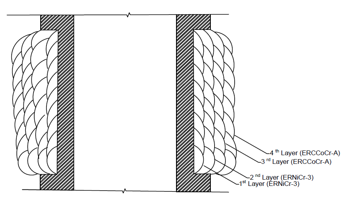
Figure 3 Double sided weld joint [2]

Figure 4 Deposition of Root and Cold passes [5]
5. SAW Consumables for Duplex Stainless Steels
5.1 Wire classifications and matching
SAW filler wires for duplex and super duplex grades are generally based on conventional duplex GTAW/GMAW
consumables (e.g. 2209, 2594) adapted to the SAW process. Typical designations include:
Technical brochures from producers show SAW wires specifically intended for duplex applications, with
classification systems according to EN ISO 14343 and related standards. For pressure vessels, matching or
slightly over‑matching PREN and strength are standard practice.[4][3]
5.2 Flux types: basic vs acidic
Research on duplex weldments and broader SAW flux studies show:
Basic fluxes:
Tend to provide better mechanical properties and reduced hydrogen content.
Support higher toughness in welded joints and HAZ.
Help maintain alloy content (Cr, Mo) and PREN in weld metal, though basicity and oxygen potential
must be tuned.[8][5]
Acidic fluxes:
Typically offer better slag detachability and bead appearance.
May promote higher oxygen levels and greater depletion of Cr and Mo from weld metal, reducing
pitting resistance.[8]
For duplex pressure vessels in aggressive media, fluxes with controlled basicity and designed for duplex
or super duplex are strongly preferred. Some producers provide flux–wire combinations explicitly qualified for
pressure vessel and power generation service.[3][5]
5.3 Nitrogen and other microalloying considerations
To counteract nitrogen loss during SAW and to support adequate austenite re‑formation:
Filler wires often contain increased nitrogen and nickel compared with the base metal.
Some fluxes are formulated to minimize nitrogen loss or even provide nitrogen pickup.
Inadequate consumable selection can lead to reduced PREN and corrosion resistance even if
mechanical test results appear acceptable.[3][5][1][8]
A welding engineer should request MTCs (Material Test Certificates) and detailed composition for both
wires and fluxes and verify that the combined weld metal composition meets project requirements
(including PREN and N content) after accounting for expected dilution.
6. Mechanical Properties of SAW Duplex Joints
6.1 Tensile properties
Across a wide body of research, SAW welds in duplex steels, when properly executed, demonstrate:
Yield and tensile strengths at least matching the base metal, often over‑matching due to higher ferrite
content and solid solution strengthening.[7][1][8][2]
Adequate ductility for structural and pressure vessel requirements, though ductility drops as ferrite
fraction rises and σ phase forms.
Studies on duplex joints produced by arc welding processes show that weldments can retain or even exceed
base metal tensile strength, provided that alloy depletion (Cr, Mo) is controlled and appropriate microstructure
is achieved.[8]
6.2 Toughness and hardness
Toughness is sensitive to:
Ferrite–austenite balance.
Presence of σ and χ phases.
Heat input and cooling conditions.
In double‑sided single‑pass SAW of 2205, a significant increase in microhardness was observed in the centre
of the leading weld seam, associated with σ phase and altered microstructure. Impact toughness tends to drop
with increased ferrite fraction and intermetallics, particularly at low temperatures.[2]
Maximum hardness requirements from standards (e.g. for sour service under NACE MR0175 / ISO 15156)
must be observed; careful parameter control and consumable selection are needed to keep hardness
below specified limits while maintaining strength.
6.3 Fatigue and fracture behaviour
Several studies on arc‑welded duplex joints (SMAW, GMAW, SAW) report:
High fatigue strength in weld metal and HAZ due to the high strength of duplex steels, provided that weld
profile, residual stress, and surface condition are controlled.
Fracture behaviour typically ductile in weld metal with well‑balanced microstructure; mixed fracture modes
appear when σ phase is present near the fusion line or where defects exist.[8][2]
For pressure vessels subject to cyclic pressure and thermal loading, particular attention must be paid to
weld toe geometry, residual stress management, and NDT to avoid crack initiation from fabrication defects.
7. Corrosion Behaviour of SAW Duplex Weldments
7.1 General and localized corrosion
The corrosion performance of SAW welds in duplex steels is dominated by:
Local alloy depletion (Cr, Mo, N) in weld metal and HAZ.
Ferrite–austenite balance and morphology.
Presence of σ phase, secondary austenite, and nitrides/carbides at phase boundaries.[1][7][2][8]
Research on duplex weldments in chloride environments shows:
Weld metals with reduced PREN (through Cr/Mo/N loss) exhibit lower pitting resistance, with pit initiation
often occurring in the weld metal or HAZ under critical conditions.[8]
Nonetheless, when flux and wire are optimized and parameters controlled, SAW welds can achieve pitting
corrosion resistance comparable to or better than hot‑rolled base plate, even at relatively high heat inputs,
as demonstrated in high‑heat‑input duplex additive processes.[1]
7.2 Effect of flux composition
Work on coated electrodes and submerged arc flux formulations demonstrates that:
Basic flux systems (higher basic oxides) generally provide welded joints with better mechanical properties
and more favourable corrosion performance, due to improved retention of Cr and Mo and better control of
slag chemistry.[8]
Acidic fluxes may result in lower PREN and heightened susceptibility to localized corrosion, although they
provide advantages in operational behaviour (slag detachability, arc stability).[8]
For pressure vessels in seawater or process brines, flux selection must be conservative. Where possible,
laboratory pitting and crevice corrosion testing should be performed during WPS qualification to verify weld
metal PREN and corrosion performance.
7.3 Sour service and standards
For sour service pressure vessels, compliance with NACE MR0175 / ISO 15156 and NACE MR0103 / ISO 17945
is mandatory. These standards:
Impose restrictions on maximum hardness.
Limit microstructural features such as excessive ferrite or intermetallic.
Sometimes restrict heat treatments after welding.[6]
Super duplex grades such as S32750 (1.4410) are often selected for sour service; producers emphasize that
welding must maintain the solution‑annealed condition of the material through adequate heat control and, where
applicable, post‑weld heat treatment.[6]
8.1 Base material and joint design
For a duplex pressure vessel, the welding engineer should:
Identify the exact base material grade, product form, and heat treatment condition
(e.g. 2205 plate to ASTM A240 or EN 10028‑7, super duplex 1.4410 to relevant standards).[9][7][6]
Select joint geometry suited to SAW:
For thick sections, double‑sided bevel or U‑joint with backing strip or back‑gouging.
For very thick shells, narrow‑gap configurations with multi‑wire SAW to balance accessibility
and heat input.
Consider fabrication tolerance, distortion control, and access for NDT.
8.2 Selection of SAW process set‑up.
Key process decisions include:
Number of wires: single‑wire, tandem, or multi‑wire.
Single‑wire offers better process control but lower productivity.
Tandem/multi‑wire boosts deposition rate but increases total heat input and complexity; tighter
heat input control is necessary.
Polarity and current mode:
Flux feeding and handling:
Apply appropriate drying regimes according to manufacturer instructions to minimize hydrogen and maintain
flux properties.[5][3]
8.3 Parameter window (example framework)
For a standard duplex 2205 longitudinal shell weld in a pressure vessel, a typical SAW WPS window might
be structured along the following principles (values indicative; actual values must be determined experimentally):
Heat input:
Travel speed:
Adjust to achieve required heat input and penetration; too slow leads to excessive heat input and
intermetallic risk, too fast leads to high ferrite and incomplete austenite re‑formation.
Interpass temperature:
Preheat:
Normally not required for duplex steels; some procedures specify a minimum temperature just above
ambient to prevent condensation (e.g. 20–50 °C), but not classical preheat.
Bead sequence:
8.4 Filler and flux selection
For each joint:
Choose wire type (e.g. 2209, 2594) with composition slightly over‑matching base metal in PREN and
N content, verified by supplier documentation and test welds.[4][3][6]
Select a flux qualified for duplex or super duplex, with:
Appropriate basicity to support mechanical and corrosion performance.
Proven performance in pressure vessels and, when necessary, sour service.[3][5]
Qualify the wire–flux combination by:
Chemical analysis of all‑weld metal to confirm Cr, Mo, N, Ni and PREN.
Mechanical and corrosion testing representative of service conditions.
9. WPS Qualification and Quality Control
9.1 Standard framework
Pressure vessel welding procedures for duplex steels should be qualified under applicable codes, typically:
ASME Section IX for WPS/PQR qualification.
ASME Section VIII Division 1 or 2 or EN 13445 for vessel design and fabrication requirements.
EN ISO 15614‑2 or related standards for duplex stainless steel welding procedure qualification in European
contexts.
For sour service, NACE MR0175 / ISO 15156 and NACE MR0103 / ISO 17945 for material and fabrication
requirements.[7][6]
9.2 Test program
A robust PQR for SAW of duplex pressure vessels should include:
Visual and surface inspection of welds, with acceptance criteria per code.
Radiography or UT for volumetric inspection of the weld body.
Transverse tensile tests across the weld.
Bend tests (face, root and side) to evaluate ductility and fusion.
Charpy V‑notch impact tests in weld metal and HAZ at specified design temperatures.
Hardness mapping in weld metal and both HAZs; verify compliance with code and sour service limits.
Metallography:
Quantitative ferrite–austenite measurement in weld metal and HAZ.
Examination for σ and χ phases, nitrides and carbides.
Corrosion testing where required:
Pitting corrosion tests in chloride media (e.g. critical pitting temperature, CPT) for judgements on PREN
and local corrosion resistance.[6][1][8]
Optional intergranular and crevice corrosion tests depending on service.
9.3 Production quality control
In production, the welding engineer should implement:
Verification of heat input and interpass temperature for a defined percentage of joints
(or all joints in high‑criticality service), with recorded WPS parameters.
Regular checks of flux condition (moisture, contamination) and wire feed quality.
Welder/operator qualification specifically on duplex SAW joints of similar thickness and position.
NDT as per code and project specification, with increased sampling in areas of high restraint or complex
geometry.
10. Common Defects and Failures in SAW Duplex Welds
10.1 Microstructural defects
Excessive ferrite due to low heat input, high cooling rate, or nitrogen loss:
σ and χ phases due to prolonged exposure in the 600–900 °C range:
Frequently associated with high heat input and repeated thermal cycles in thick multi‑pass welds or
double‑sided single‑pass procedures.[6][2]
Cause increased hardness and reduced ductility and corrosion resistance.
Cr₂N and carbides precipitated at ferrite–austenite interphase boundaries:
Result from nitrogen supersaturation followed by subsequent decomposition on slower cooling or reheating.[7][8]
10.2 Conventional welding defects
Typical welding defects (lack of fusion, slag inclusions, porosity, undercut, arc strikes) occur as in any
SAW process. However, their impact is amplified in duplex pressure vessels due to high service severity.
In thick duplex SAW welds, lack of fusion in sidewalls or between beads is a particular risk when
travel speed is too high or the joint design is too narrow for the selected parameters.
Slag inclusions may arise from insufficient inter‑pass cleaning or inappropriate flux handling.
Porosity is generally less common in SAW but can arise from high flux moisture or contaminants.
10.3 Service failures and case histories
While detailed case reports are often proprietary, the literature and industrial guidelines consistently indicate that:
Most service failures in duplex stainless pressure equipment are related to incorrect material
selection, improper welding (overheated welds, wrong consumables), or post‑fabrication heat
treatment that promotes intermetallics, rather than inherent material deficiencies.[9][7][6]
When SAW welding procedures are correctly developed and implemented, duplex pressure vessels achieve long
service life with minimal corrosion and mechanical failures.[9][6]
11. Comparison of SAW with Other Processes for Duplex PV Fabrication
Although the focus is SAW, welding engineers often combine multiple processes:
GTAW/GMAW:
Used for root passes and attachments in duplex vessels.
Offer excellent control, but lower deposition rates than SAW.[10][7]
SMAW and FCAW:
Employed for site erection, repairs, or locations not accessible by SAW.
Flux‑cored wires (e.g. 2209, 2594 cored) are widely used in duplex fabrication.[4][5]
SAW:
Primary choice for long seams and circumferential welds on shells and heads, due to high
deposition rates and productivity.[3][5][9]
Particularly advantageous in automated vessel shops with positioners and welding manipulators.
A typical fabrication strategy uses:
12. Practical Recommendations and Checklist for Welding Engineers
12.1 Planning and design stage
Confirm design conditions (pressure, temperature, medium, presence of H₂S/CO₂/chlorides) and required
compliance (ASME/EN, NACE, ISO).
Select duplex grade (lean, 2205, super duplex 2507/S32750/S32760) based on corrosion and strength
requirements.[9][7][6]
Choose joint designs compatible with SAW and accessible for NDT.
12.2 WPS development and qualification
Select duplex‑qualified SAW wires and fluxes, verify supplier data for:
Alloy composition and PREN.
Approved applications, including pressure vessels and sour service if applicable.[4][5][3][6]
Establish a parameter envelope for:
Heat input.
Interpass temperature limits.
Wire feed speed and travel speed for each pass type (root, fill, cap).
Qualify the WPS with full mechanical, metallurgical, and corrosion testing appropriate to service, ensuring:
Balanced ferrite–austenite ratio.
Absence or minimal presence of σ/χ phases.
Acceptable hardness and pitting resistance.
12.3 Production control
Train operators in duplex SAW specifics (no preheat, strict interpass control, flux handling).
Monitor and log welding parameters for critical joints and random sampling for others.
Maintain flux in dry, clean conditions; use recommended baking/holding temperatures.
Perform NDT and inspections as required; use additional metallography or corrosion tests on
surveillance coupons when justified.
12.4 Repair and modification
Develop dedicated repair WPSs to avoid excessive reheating and intermetallic formation.
Prefer lower heat input processes (GTAW, GMAW) for local repairs where feasible.
Limit repair cycle count in the same region; where repeated repair is unavoidable, consider localized
solution annealing for some components, subject to code and material limitations.
13. Conclusions
Submerged arc welding is a highly productive and technically suitable process for the fabrication of
pressure vessels in duplex and super duplex stainless steels, provided that it is implemented within a
carefully defined and verified process window.
The critical success factors are:
Metallurgical control: maintaining balanced ferrite–austenite microstructure and preventing intermetallic
phase formation by controlling heat input, interpass temperature, and overall thermal history.[1][7][2][6][8]
Consumable engineering: using SAW wire–flux combinations specifically designed for duplex steels, with
adequate Cr, Mo, N and Ni to deliver weld metal with appropriate PREN and mechanical properties.[4][5][3][6]
Code-compliant procedure qualification: comprehensive testing (mechanical, metallurgical, and corrosion)
aligned with ASME/EN pressure vessel codes and NACE/ISO requirements for sour service.
Rigorous shop practice and quality assurance: consistent parameter control, flux conditioning, welder/operator
qualification and thorough NDT.
When these elements are in place, SAW welds can provide long‑term, reliable performance in the highly demanding
environments where duplex stainless steel pressure vessels are specified, matching or exceeding the performance of the
base material and offering substantial life‑cycle cost advantages over conventional materials.[7][9][6]
References
https://www.sciencedirect.com/science/article/abs/pii/S092401362500175X
https://ui.adsabs.harvard.edu/abs/2013JMEP...22.2477L/abstract
https://cdnstorevoestalpine.blob.core.windows.net/image-container/729472/original/Submerged_Arc_Welding_Fluxes_and_Wires.pdf
https://www.hyundaiwelding.com/data/file/download/brochures/HYUNDAI_FCAW for Stainless Steel (BROCHURE).pdf
https://tedelbi.com/wp-content/uploads/2021/01/Duplex-Welding-Guidelines.pdf
https://bach-industry.com/super-duplex-1-4410/
https://nickelinstitute.org/media/8dab1e8a1825480/nickelpub10044_apracticalguidetousingduplex.pdf
https://www.nature.com/articles/s41598-022-26974-6
https://www.titanmf.com/products/pressure-vessels/duplex-stainless-steel-pressure-vessels/
https://pmc.ncbi.nlm.nih.gov/articles/PMC11547027/


Comments
No comments available.