
News release
Perfect Welding
Anton Paar GmbH
Fit for the future thanks to smart robot welding technology
Pursuing progress and innovation in consultation with the customer, trendsetting Austrian company Anton Paar manufactures high-precision measuring devices for a wide range of industries. Its dedicated research, engineering, and production teams aspire to keep pushing the boundaries of what’s possible. Today, Anton Paar GmbH is the world leader in density and concentration measurement, rheometry, and the analysis of dissolved CO2. A growing shortage of skilled workers and ever-increasing quantities call for intelligent production solutions, so the company invested in a latest-generation robotic welding cell.
Up until now, all components of the measuring and control devices Anton Paar produces in Graz, Austria have been welded by hand. This was because robotic welding systems were deemed uneconomical for small batch sizes between one and 400 pieces. Ongoing sales growth, the increasing shortage of skilled workers in the domestic job market, and innovative robot technologies—which now make automated welding economically viable even for small batch sizes—prompted the high-tech company to invest in a modern robotic welding system. The measurement and control specialists at Anton Paar were looking for flexibility all along the line, combined with a high degree of cost effectiveness. This meant flexibility in terms of the number, shape, and size of the components, in their positioning, and in the use of different welding processes.
Dominik Santner, COO at Anton Paar GmbH, says, “The shortage of skilled workers and ever-increasing quantities call for new solutions in production. The new robotic welding cell represents a huge step towards automation of our manufacturing. If we were to weld our process sensors manually like before, we would encounter huge difficulties achieving the planned quantities in the coming years.”
Autonomous welding and a broad range of components
From the outset, the emphasis has been on system autonomy for the experts at Anton Paar. Once set up, the welding system needed to be able to process a complete order from start to finish in a single pass. For example, welding a batch of different objects such as oscillator housings, main carriers, or countercoolers. And the system had to be able to do this completely independently and without the intervention of welding specialists.
A range of factors made designing the system especially challenging for engineering and programming teams, including components of various shapes, weights, and sizes, different gripping, positioning, and storage possibilities, the option to use two different welding processes (TIG and MIG/MAG) on a single component, as well as the use of forming gas to protect the components against tarnishing, which is necessary for cylindrical bodies.
“We were looking for a reliable partner who was very similar to us in terms of precision and quality. We wanted someone who would really listen to us, respond to our preferences, and propose sustainable solutions. A partner that would give us a competitive edge for years to come,” explains Daniel Moik, department manager for joining technologies. “Fronius International met these criteria for a sustainable partnership. In close cooperation with our technicians, the welding automation team developed a robotic welding cell that meets our requirements in every respect. On top of that, Fronius is ready to work with us to evolve the system and adapt it to new needs.”
Synonymous with efficiency: Fronius Pathfinder
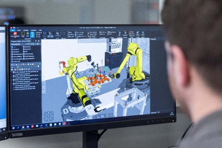
At Anton Paar, new welds are programmed offline—away from the welding system—rather than directly on the system, as is often the case. Rather than stopping ongoing welding work, welding continues during programming, increasing productivity. The welding technicians create the conditions for this by importing the CAD data of the measuring device components to be welded into the Fronius Pathfinder®. Various joining scenarios are then tested and welding sequences are defined and optimized in the course of simulations.
Starting points, work angles of the welding torches, torch offsets in the corner areas, and all reorientations of the welding robot are all taken into account during these simulations. Pathfinder identifies instances where the robot range is exceeded, known as axis limits. By the software operators correcting the storage location of the workpiece and positioning it within arm’s length of the welding robot, potential collisions between the torch and various component edges are avoided at an early stage.
Sources of errors are identified in good time
If the track needs to be corrected, the affected teach points can be easily moved by dragging and dropping them. When the approach to the component needs to be changed, the specialists simply press “Reset.” The virtual robot then moves to the home position to start a new approach run. Under real-life conditions, operators would have to complete the time-consuming process of retracting the robot, moving it to the home position with the robot controller, and restarting the teaching process. By opting for the Pathfinder offline programming and simulation software, the experts at Anton Paar not only gain valuable time for welding work but also identify sources of error ahead of time.
Once a welding program has been set up in Pathfinder, it is translated by a so-called post-processor into the specific code of the Fanuc welding robot. It can then be transferred to the welding system via data transfer using a LAN connection, for example. A key feature that provides effective support for production planning as a whole is the “Determination of cycle time” function, which includes welding speeds as well as gas pre-flow and end crater filling times. Compared to teaching with the robot controller, Pathfinder can achieve a time savings of up to 90%, depending on the component geometry and welding requirements.
Customized for Anton Paar
Anton Paar has access to custom workflows for welding its many different components, including the three main workflows, which are a prime example of the incredible flexibility in the range of components.
Workflow 1: The components are welded on the turn-tilt positioner. A pallet loaded with components is removed from the pallet rack and temporarily stored on a pallet storage table. The handling robot then attaches a suitable gripper for picking up components, with six different ones being kept in what is known as a gripper station. Equipped with the gripper, the handling robot picks up the components and fixes them in a component-specific clamping device, which is already installed on the manipulator. The robot always removes one component at a time, which is then joined and returned to the pallet.
Workflow 2: The components are welded directly on the pallets, with the handling robot transporting the pallets from the pallet rack and positioning them in front of the welding robot. The handling and welding robots can then perform coordinated movements together during the welding process, enabling them to weld not just simple seam geometries but complex ones as well.
Workflow 3: The components are removed individually, positioned by the handling robot, and move in sync with the welding robot during welding. This is called “coordinated motion.”
Making sure the system knows what to do
In addition to the innovative Fronius welding technology, controls, tool center point (TCP) measurement, torch cleaning station, and enclosure, the robotic welding system consists of seven core modules that collaborate on the basis of software control. These consist of a handling robot, a welding robot, a turn-tilt positioner with forming gas unit, a pallet store with two racks, a gripper station, a torch changing system, and a pallet repository inside the system. The following steps are required in order for those modules to interact precisely during the working cycles.
First, pallets and components are created together in the HMI-T21 RS system controls, which are provided with four important pieces of information by the relevant welding specialist: (1) the pallet type and (2) the type, (3) the number, and (4) the position of the components on the pallet—for example, how many main carriers or oscillator housings are located in which position on which pallet. If it is an offset pallet, the component position is calculated on the basis of the so-called offset distances between the components, with the first component assuming the master position. For example, an offset might be 200 mm on the y-coordinate and +200 mm on the x-coordinate. The pallets manufactured by Anton Paar consist of perforated plates that are centimeters thick and function as a plug-in system. They are located in a pallet store consisting of two racks and are designed to accommodate each of the different workpieces, with the receiving and depositing positions of individual components often varying depending on the nature of the component and the gripper of the handling robot.
The robot controller contains a hierarchically superordinate robot program for each workflow type. This is where the welding programs created with Pathfinder are stored. If a pallet for Workflow 2 is created on the HMI (components are welded directly on the pallet), the robot controller filters the corresponding robot welding programs, and Anton Paar’s welding specialist can conveniently choose between all the programs that are available for Workflow 2 and assign the right one to the pallet. There is also the option to not only use a single welding program but also create an entire work sequence. For example, a TIG program can be created for a pallet, followed by a MAG program (e.g., CMT) in the same sequence. In this case, the robotic welding system would execute both programs one after the other and automatically change the welding process. In addition, the experts at Anton Paar can insert certain special steps into the HMI process. For instance, the system knows the special “Turn component” step, which can be used between the two welding processes (TIG and CMT) if necessary.
If a specific gripper is required for pallet handling, as described in Workflow 1, the system operator must select it in the system. As previously mentioned, there are a total of six different grippers available, all of which are kept in a gripper station.
Teaching gripping and depositing positions
The conventional handling sequence itself—picking up the pallet, positioning it for welding, transporting it back, and depositing it—is a standard program and requires no intervention from the operator. This is referred to in the field as an “encapsulated” function. Only the gripping positions have to be specified.
If a new component is “moved in” and not recognized by one of the depositing or receiving stations, the automatic run pauses. The welding specialist is prompted to start a teaching process with the robot controller—the Fanuc iPendant—and receives step-by-step instructions from the system software. Based on this, the system “learns” the required gripping/depositing position for the relevant station (e.g., for the clipboard). This position is stored in a register and is available for the handling process from that point on. The automatic run can then continue to the next station. If the component is also unknown there, this position must also be taught. Once all the stations have been worked through as described, the handling robot transports all other identical components through the system automatically, without interruption.
If a pallet should have seven components but there are only three components on it, this is no issue for the system. It detects an “empty grip” and automatically moves to the next component position.
Custom-made: the teach pallet
In addition to the standard offset assignment, which favors simple component shapes, Anton Paar wanted to be able to deposit up to 30 metal components at any point on a pallet. Fronius responded by creating the “Teach pallet” function. Selecting this function makes it possible to separately teach the position of each component on the pallet.
“These two versions, offset and teach pallet, offer us maximum flexibility in component placement,” explains Dr. Ingo Riemenschneider, department manager for production automation. “It doesn’t always make sense for us to define component positions using offset distances. We have to fix some components in different orientations because of their complex shapes.”
As precise as on the first day—even after months
When the welding specialists want to start a welding process, they use their handheld scanner to scan the item number on the component data sheet.
“If the system detects the item number and thus the component, it knows about the handling and welding process and starts operation. Everything is controlled via the HMI-T21 RS. The system stores which gripper and which device are needed for each of the components,” explains Riemenschneider. “The same applies to the argon flushing time during forming and the seam time. The system also knows whether and what data is required for process data recording.”
Months later, the robotic welding cell is still just as precise as on the first day, and the weld seam is perfectly positioned in the same place. This can also be attributed to the fact that Anton Paar manufactures the components with micrometer precision and joins them with an exemplary level of quality.
Components can be turned multiple times—even during forming
The turn-tilt positioner has a media conduit for four flow-through lines, two for air and two for argon, and can transmit up to 32 input-output signals (IOs). It is made of plastic and was produced by Anton Paar using 3D printing. If components need to be formed, the handling robot first retrieves the required clamping device from the pallet rack and clamps it on the manipulator with the help of a special clamping system. From that point on, both the air lines for the pneumatic cylinders and the gas lines for flushing with argon are connected. The electrical signals are now also transmitted by the clamping device. The handling robot then positions the components and the system sends the signal for clamping. Forming can now be carried out, followed by welding. The system is designed in such a way that the components can be turned several times on a single clamping device.
“It is important to us that all processes and properties that were implemented in the system are open in terms of their repeatability. The matter of whether a turning process is carried out once or a hundred times has to be irrelevant from the perspective of the system. Given that the complexity of our components is constantly changing, we and the experts at Fronius put a lot of energy into making the processes as unrestricted as possible,” notes Riemenschneider.
Residual oxygen measurement made by Anton Paar
When forming on the tilt-turn positioner, the residual oxygen in the component is measured with the company’s own Oxy 5100 measuring device. It carries out drift-free measurement of the dissolved oxygen in the gas stream in real time during the entire welding process. Normally, the component is fixed between two sections of a line. The forming gas flows in on one side, on the supply line, and out again as a flow of exhaust gas on the other side, where the residual oxygen content is measured. This procedure would be counterproductive for the automated welding process, as the robot would have to take the extra step of inserting and removing an exhaust gas hose during each welding process. The decision was therefore made to place the measuring device in the supply line. As soon as the device reports that the desired residual oxygen content has been reached, welding is started, taking into account a time delay for the time it takes the argon gas to flow through the component. This period is needed to ensure that the required residual oxygen content is not exceeded. The time it takes for the component to be completely filled—the time delay—is determined for each of the components based on a manual measurement and stored in the system. If the component comes up again, the controller can access the values and respond accordingly.
At the apex of welding technology
It was particularly important for Anton Paar’s welding specialists to be able to combine two welding processes for a component—for example, TIG for welding the root pass and MAG for welding the final run. However, the final choice of welding method depends on the welding calculations and the required resistance of the individual components.
“Our welding tests are the deciding factor in whether we use special processes such as CMT (cold metal transfer), PMC (pulse multi control), or LSC (low spatter control). The process we then decide on depends on the wall thickness of the component, on the type of weld, for example square butt or fillet weld, and on the required welding depths and micrographs,” Moik explains. “We need about six or seven tests before we go into series production.
If the heat input would be too great due to the nature of the material, the CMT ‘cold’ welding process is of course suitable. If we want to boost productivity by increasing the welding speed, we look at PMC. If welding needs to be particularly low spatter, LSC might be a good choice, primarily because this prevents expensive rework.”
The welding data is recorded in the HMI. If the welding specialist finds a fault during the visual inspection, they can check the welding data record to see whether there have been any deviations from the limit values. Every component is subjected to a visual inspection (VI) as a matter of principle, and every tenth component undergoes a color penetration test (PT). This method can be used to detect cracks, pores, and lack of fusion of down to 1 µm. The PT-tested metal components are regularly subjected to micrographs at the end of the test cycle.
The innovative Fronius processes, a system concept that is both intelligent and flexible, and the ongoing potential to continue developing the robotic welding system ensure that Anton Paar’s sensitive, high-precision measuring devices will have perfect weld seams for years to come. The company’s welders simultaneously benefit from increased safety and protection of their health as they are shielded from the arc and its emissions by the enclosure and extraction system.
15.537 characters excluding spaces
This news release and the images can be downloaded from: https://www.fronius.com/en/welding-technology/info-centre/press
Copyright to photos: Fronius International GmbH, reproduction free of charge
Images
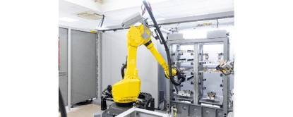
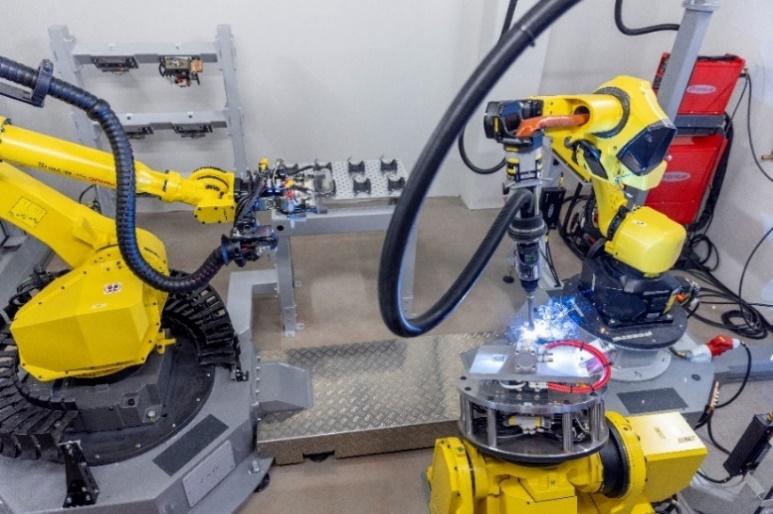
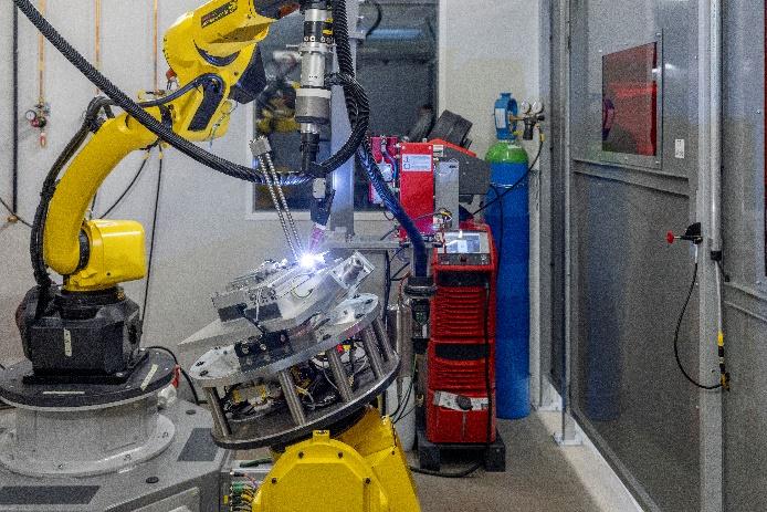
Robotic welding cell: TIG welding is performed on so-called main carriers; handling robot positions the pallet with components

Dominik Santner
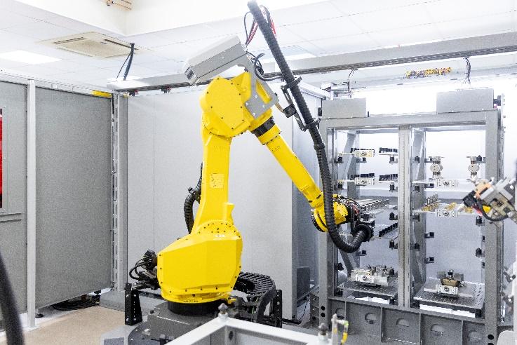
Handling robot: Fully automated removal of components and clamping devices from the pallet rack

Daniel Moik
Programming welding sequences and simulation using Fronius Pathfinder
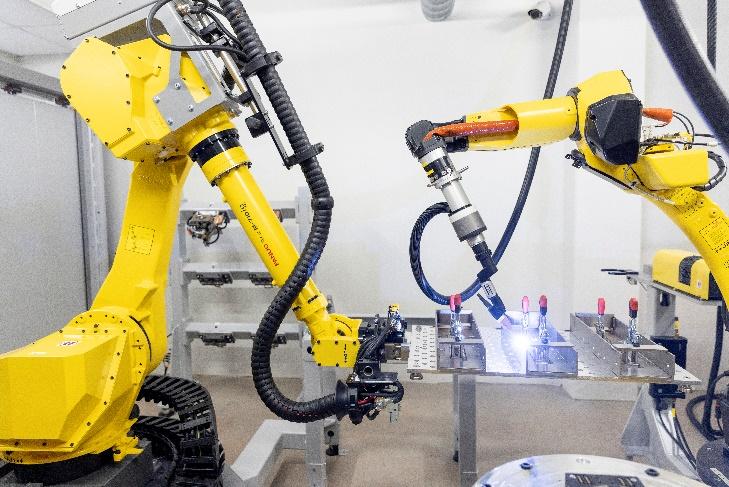
CMT welding of countercoolers on the tilt-turn positioner, with pallet repository in the background
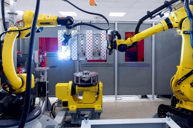
Oscillator housings are welded on pallets using the CMT process; coordinated movement sequences of handling and welding robots
CMT welding, handling robot moves the component into position

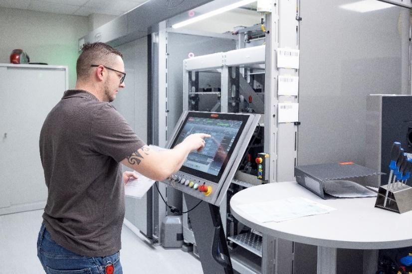
Daniel Moik creating a pallet on the touchscreen of the HMI-T21 RS

A pallet filled with components is removed from the pallet rack
Pallet storage with components and clamping devices


Handling robot picks up a new gripper
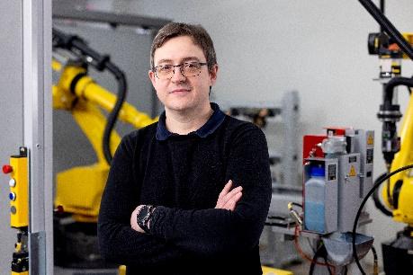
Ingo Riemenschneider
TIG welding of countercoolers with residual oxygen measurement

Daniel Moik carries out a visual inspection of a fully welded oscillator housing

Modular compact rheometers for characterizing the material properties of liquid to solid substances
We are Fronius.
Over 8,000 employees worldwide, a current export share of 87 percent, and 1446 active patents: that’s us, that’s Fronius. Founded in 1945 as a regional one-man operation, we are now a global player – a fact that is impressively demonstrated by our 37 international subsidiaries and our network of sales partners in more than 60 countries. And yet, at our core, we are still a family-owned company from Austria, active in photovoltaics, welding, and battery charging technology. We have always developed products and solutions for a future worth living, offering our customers an all-in-one package in the process: from advance planning and consulting to ongoing monitoring and a repair service tailored to their specific needs. We are innovative. We are curious. We are Fronius.
We are Perfect Welding.
Maximum arc quality, a deep understanding of our customers, a thirst for technical progress: this is what drives us at Fronius Perfect Welding. We are the innovation leader for arc welding and the global market leader for robot-assisted welding. Our customized, automated complete systems and digital welding solutions for Industry 5.0 are the product of our expertise. Intuitive welding systems for manual welding applications, high-quality welding accessories, and effective protective products to keep users safe round off our portfolio. As a global company, we offer regional service through local teams who are on hand for our customers around the world. Our technologies break new ground and form connections – between metals, industries, and people.
For more information, please contact:
India:
FRONIUS INDIA PVT. LTD; Pranjali Ghanekar
Plot no. BG 71/2/B, Pimpri Industrial Area, MIDC Bhosari,
Pune – 411026, Maharashtra, India
Phone: +91 73910 87915
E-Mail: marketing.india@fronius.com
Fronius International:
Frau Heidemarie Haslbauer Tel.: +43 (664) 88293709,
E-Mail: haslbauer.heidemarie@fronius.com
Please send an author’s copy to our agent:
a1kommunikation Schweizer GmbH, Frau Kirsten Ludwig,
Oberdorfstraße 31 A, 70794 Filderstadt, Deutschland
tel.: +49 0 711 9454161-20,
e-mail: kirsten.ludwig@a1kommunikation.de
For more exciting updates, visit our blog at blog.perfectwelding.fronius.com and follow us on Facebook (froniuswelding), LinkedIn (perfect-welding), Instagram (froniuswelding) and YouTube (froniuswelding)!


