S A David
Group Leader & Corporate Fellow
Emeritus

J M Vitek
Distinguished Scientist (RTD)

Z Feng
Group Leader, Materials joining
Oak Ridge National Laboratory, Oak Ridge, TN 37831, USA
(Notice: This manuscript has been authored by UT-Battelle, LLC, under contract DE-AC05-00OR22725 with the US Department of Energy (DOE). The US government retains and the publisher, by accepting the article for publication, acknowledges that the US government retains a nonexclusive, paid-up, irrevocable, worldwide license to publish or reproduce the published form of this manuscript, or allow others to do so, for US government purposes. DOE will provide public access to these results of federally sponsored research in accordance with the DOE Public Access Plan (http://energy.gov/downloads/doe-public-access-plan) )
ABSTRACT
Welding is developing more as a science than as an art. In the last four decades welding has seen an enormous growth in applications. It is a complex process with a number of coupled parameters. A science-based technology to produce welds of highest quality and performances is possible with the advancements in welding techniques, analytical methodologies, and computer power. All these developments will aid in the advancement of intelligent weld manufacturing, whose ultimate goal is to control weld penetration, defects, and ultimately, microstructures, properties, and performance.
The paper discusses various physical processes involved in welding such as melting, vaporization of elements, solution of gases, solidification, microstructure, residual stresses, and briefly mentions sensing, control, and automation.
The practice of welding dates back to prehistoric times, when people soldered with copper-gold and lead-tin alloys [1].Welding is the technology of joining by melting and fusing of metallic parts together. Welding mostly includes the formation of metallurgical bonds in various brazed-soldered or fused joints but excludes joints made by mechanical means (bolts, nuts and rivets). However, in friction and ultrasonic welding, a metallurgical bond is created by mechanical working of the material without melting. Since the invention of welding, a corresponding dedicated branch of science has evolved to understand welding processes and the behavior of metals subjected to the weld thermal cycle and to refine and expand its applications.
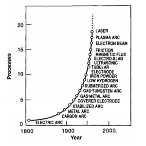
The development of modern welding technology began in the latter half of the 19th century, when electricity became readily available [2]. Figure 1 shows development of various welding processes based on the heat sources used. The predominant heat source is the electric arc. Within the arc welding process, the classifications are based on shielding and filler metal additions. Examples include gas tungsten arc welding, gas metal arc welding, and submerged arc welding. In the last few decades the development of high-energy heat source processes such as electron-beam and laser welding has enabled welding of metals and alloys that have a high melting point.
Fusion welding is used extensively in construction, automobile, aircraft, aerospace, and shipbuilding and energy and electronics industries and affects an estimated 50% of the United States gross national product [3]. In the last few decades welding has evolved as an interdisciplinary activity requiring a combination of knowledge from various basic and applied sciences. Specialists in diverse disciplines such as arc and plasma physics, thermodynamics, materials sciences, metallurgy, mathematical modeling, computer science, robotics, economics, and a variety of engineering fields such as mechanical, electrical and chemical engineering are making new contributions [4]. Some of the researchers in the United States who have made and continue to make significant contributions to welding science and technology are S. S. Babu, G. Cook, S. A. David, T. DebRoy, J. N. DuPont, T. Eagar, J. W. Elmer, Z. Feng, S. Kou, J. Lippold, S. Liu, D. L. Olson, H. B. Smartt, J. M. Vitek, T. Zacharia, M. Zhang, W. F. Savage (late), and J. Szekely (late).
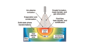
In the fusion welding process a heat source interacts with the metallic parts, which undergo local melting and fuse together as they cool. Figure 2 shows the interaction of the metal with the heat source and the three distinct regions of a weldment, namely the fusion zone (FZ), which undergoes melting and solidification; the heat-affected zone (HAZ),which experiences heating and cooling during the weld thermal cycle but does not experience melting; and the base metal (BM), which is not affected by the weld thermal cycle. (Figure 3a).
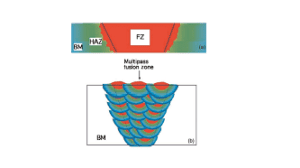
Welds can be completed in a single pass or in multiple passes, with or without the addition of filler metal, depending on the thickness of the parts. (Figure 3b). In a multipass weld, filler metal is added layer by layer. The practice of layer-by-layer addition of filler metal is being used in the newly developed technology of additive manufacturing [5, 6]. There are many similarities between welding and additive manufacturing [7, 8].
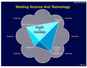
Like any other processing, welding has the goal of producing products of the highest quality and integrity. To achieve that goal, four key elements must be thoroughly understood:(1) process and process modeling, (2) microstructure, (3) properties, and (4) sensing control and automation. Figure 4 shows the integration of all these elements [9].The ultimate goal of intelligent weld manufacturing depends on the integration of models for welding. In order to do this, an integration of the four key elements mentioned earlier is necessary. Such an integration of models with sub-models is a great challenge.
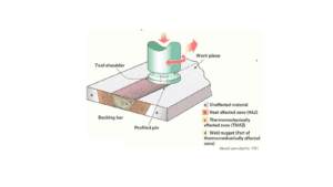
In the last four decades significant advances have been made in welding and welding processes (e.g., keyhole plasma welding, magnetic pulse welding, transient liquid phase bonding, laser/arc hybrid welding, and friction stir welding [FSW]). FSW has received the most attention among the recently developed welding methods [10]. FSW is a novel welding process invented by Wayne Thomas of The Welding Institute, Cambridge, UK, in 1990. It is a solid-state welding process involving plunging a rotating tool with a pin at a high angular speed into a joint between two plates and traversing it along the line where the weld is to be made. The frictional heat generated by the rotation of the tool on the joint plasticizes the metal, and metal flow creates a metallurgical bond. Figure 5 shows a schematic of the FSW process. Another process of interest is the laser/arc hybrid welding process, which improves the quality of the weld and the efficiency of the welding process [11].Although it is an older process, it is getting a lot of renewed attention from industries as a means to improve quality and productivity. The various physical processes involved in FSW will not be discussed in this paper.
In the 1940s welding methods were not supported by much rigorous scientific underpinning (it was more of an art than a science).In the 1950s through the 1970s a discipline was developed to scientifically determine the behavior of materials (nonferrous and ferrous alloys)exposed to the weld thermal cycle. In the last three to four decades we have seen enormous progress in analytical and numerical models to describe welding and to identify the parameters that govern the use of welding as a means to join an increasing variety of alloys.
This paper was prepared in an effort to summarize basic information on welding and the behavior of metals and alloys subjected to the weld thermal cycle. It addresses the current state of fusion welding in terms of the developments in processes, process modeling, microstructure, properties of weldments, residual stresses, and process control and automation.
During welding, as the heat source interacts with the metal, a number of physical processes occur, such as melting, vaporization, solution of gases, solidification, solid-state phase transformation, and development of residual stresses and distortion. These events influence the structures and properties of the weldments. Significant advances have been made in understanding various physical processes and their influence on microstructure and properties. This is mostly due to advancements in characterization technology and increase in the availability and speed of computers.
Due to the complexity of the welding process, experimental measurements of various physical processes and their interaction is very difficult. Computer modeling and simulation have been found to be very valuable. Phenomenological modeling of welding processes has yielded significant insight into our understanding of the welding process [12, 13].
2.2 Evaporation of Elements and Solution of Gases
In welding the weld pool surface temperatures are much higher than the melting point of the weld metal. As a result, pronounced vaporization of elements from the surface of the weld pool occurs, especially in high-energy-density processes such as electron and laser welding. Such elevated vaporization results in a change in composition and properties. Efforts have been made to calculate the peak temperature on the weld pool surface; it was estimated to be 2,800 K for welding Fe-Mn alloys [14, 15]. Several other investigators have estimated the surface temperature in excess of the boiling point of the alloy [16, 17]. Comprehensive models have been developed that enable a better understanding of vaporization and change in the composition of the weldment [18,19]. The model prediction agrees with the experimental results for the laser welding of titanium, pure iron, and stainless steels.
During welding, hydrogen, nitrogen, and oxygen may dissolve into the weld metal and form pin holes, porosity or combine with elements in the alloy to form oxides. In steels hydrogen induces cracking, nitrogen increases yield strength but reduces ductility, and oxygen promotes inclusion formation. Some oxide inclusions can improve toughness by promoting the formation of acicular ferrite in steels. At the high temperatures reached during welding, reaction of oxygen and nitrogen with the weld metal is rapid, and some type of shielding is required to avoid extensive dissolution and reaction. This may be achieved by means of flux, gas, or a combination of the two, or from evacuation of atmosphere, as in electron beam welding. In submerged arc welding, the flux provides shielding of the metal from the atmosphere. The slag helps in protecting the metal. Oxygen and nitrogen contents as high as 0.7 or 0.2 wt. % respectively, have been observed in the weld metal during arc welding [20]. These concentrations are far greater than those in the BM and filler metals.
Fluid flow and heat transfer affect the size and shape of the weld pool, the cooling rate and the kinetics of liquid-to-solid transformations as well as various solid-state transformations. Significant advances have been made in calculating weld pool heat transfer and geometry. Weld pool geometry is critical in assessing weld pool penetration and the grain growth selection process [21].
In 1940s, efforts were made to mathematically model transport phenomena in welds [22-23]. The models were analytical and addressed conduction heat transfer only. As complex as it is, welding requires a more robust model. In the 1980s, significant progress was made when the concept of convection in the weld pool was introduced [24-27]. This gave a big boost to weld modeling capabilities, and numerical techniques were developed and led to the development of 3D transient models for the arc-welding process using a direct coupled simulation technique [30]. Later, a deformation of the weld pool surface in a linear weld was incorporated in models [28, 29]. Significant advances have been made in calculating the weld pool geometry [30-42]. Weld pool heat flow and fluid flow are recognized to be critical in the development of the shape and size of a weld as well as its macrostructure and microstructure. Current models address coupled conduction and convection problems to predict weld pool geometry. Of the various heat-transfer mechanisms, the convection plays a major role in determining weld pool geometry and penetration.
Convection in the weld pool is driven by surface tension, buoyancy, and electromagnetic forces [43-48].Convection due to surface tension is the dominant contributing force to the fluid flow in the weld pool. The presence of a significant temperature gradient on the weld pool surface leads to spatial variation of surface tension, also known as Marangoni stress, which contributes to convection in the weld pool. [42-49] Buoyancy effects due to spatial variation of density of liquid as a function of temperature and composition can provide convective flow. Electromagnetic forces are due to the divergent path of the current and the magnetic field that the current generates.
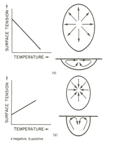
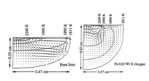
The reason that a shallow- or deep-penetration weld forms depends on the temperature coefficient of surface tension (dγ/dΤ). For pure metals and alloys, dγ/dΤ is negative (Figure 6). For a stationary arc-weld pool, the highest temperature is in the middle of the weld pool. Therefore, the hot liquid flows outward, resulting in a shallow weld pool (Figure 6). In the presence of surface-active elements such as phosphorous, sulfur, and sometimes oxygen, the dγ/dΤ is positive, resulting in the fluid flowing inward and driving the hot liquid downward, resulting in a deep weld penetration. Figure 7 shows flow fields in a shallow weld pool in pure iron (left) and a deeper penetration with addition of oxygen (right).
In the past three decades, most of the studies have concentrated on convective heat transfer, in particular, on the effect of spatial variation of surface tension on weld penetration. For simplicity, most of the earlier models assumed weld pools with a stationary arc and with a rigid weld pool surface. Recently, the models have been refined to incorporate realistic welding conditions such as a deformable weld pool surface and a moving heat source [28,29]. In the last three decades, we have seen an enormous growth in our understanding of the physical processes in welding. This is in part due to the speed and availability of computers.
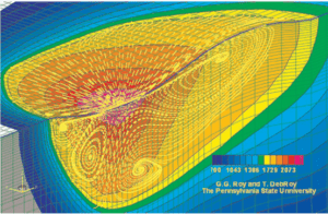
The variable penetration during welding of different batches of a commercial alloy within a prescribed range has received considerable attention [48-50]. Studies have shown that knowledge of the interfacial phenomena is the key to our understanding of and controlling of weld penetration. A computerized analysis has been developed for predicting heat flow, phase changes, and fluid flow [50]. Figure 8 shows the computed convective flow field in a weld pool during arc welding. The color represents the temperature (in degrees kelvin); the dotted lines show the liquid flow field. The two large loops shown near the surface of the weld pool are from Marangoni flow; the other loops below are from electromagnetic effects.
Two of the most important weld features in automated welding are weld pool geometry and penetration. Over the past three decades, several computational models have been developed for weld pool shape and penetration. The models have become more complex and sophisticated and require greater computational power. Although they are excellent tools for understanding the physical processes in welding, they are not available for the end users. An alternate process is to use of an artificial neural network (ANN) [51]. A publication by Bhadeshia highlights the application of neural networks in materials science [52].
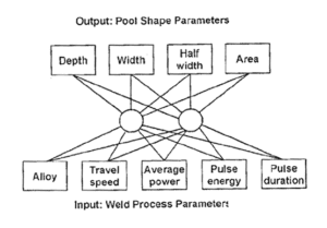
Neural networks have been used to solve problems in many areas of science and technology. Such models are empirically based and are capable of providing results rapidly. For example, in the case of the laser/arc hybrid welding process, the physics of the process is not well known even though the physics of laser-only or arc-only welding processes are understood individually. ANN modeling can be used to determine the weld pool shape [53]for the laser/arc hybrid welding process. Figure 9 shows a neural network architecture for laser/arc hybrid welding process [54]. ANN modeling has been used for a wide variety of investigations [54,55]. ANN has been used for modeling mechanical properties of steels and for diffusible hydrogen control and cracking susceptibility in flux-covered arc welding. A new model, Oak Ridge Ferrite Number (ORFN), has been developed at Oak Ridge National Laboratory for predicting ferrite content in stainless steel welds [56].
3. MICROSTRUCTURES
The integrity of the welded joints depends on the microstructures and properties of the three regions of the weldments, namely, the FZ, the HAZ, and the BM. The microstructure development in the FZ depends on the solidification behavior of the weld and on the solid-state phase transformation in the FZ and the HAZ. Efforts are underway to use analytical and numerical models to characterize the solidification behavior and the evolution of microstructure in the weld metal.
Heating, cooling and local structural changes cause spatial variations in compositions, microstructures, and residual stresses. During the past 30 years, significant progress has been made in our understanding the solidification behavior of the weld pool and the evolution of microstructure in the FZ [21]. The application of computational thermodynamics and kinetic tools has enhanced the understanding of weld solidification behavior of complex multi component systems. Advanced insitu characterization techniques have enhanced our understanding of phase formation and non equilibrium effects during weld pool solidification. The use of model alloy single crystals resulted in new insight into the role of weld pool geometry on the dendrite growth selection processes in the development of weld microstructure [21, 23, 57-59]. A recent review [60] examines the various models for microstructure development in welds using computational thermodynamics and computational kinetic models. The first event to occur during cooling of the weld pool is the formation of a solid, and the solid subsequently transforms to a multiphase microstructure through a solid-state transformation.
Most of our current knowledge of weld pool solidification is derived from an extrapolation of the knowledge and models for freezing of castings, ingots, and single crystals at lower thermal gradients and growth rates [21, 61-62]. The same parameters that are important in determining microstructures in castings, such as growth rate (R), temperature gradient (G), under cooling (ΔΤ), and alloy composition, also play significant roles in determining the development of microstructures in welds. The temperature gradient and growth rate are important in the combined forms G/R and GR (cooling rate) since they influence the solidification morphology and the scale of solidification substructure, respectively. In welding, where the molten pool traverses across the material, both G and GR vary considerably across the FZ, and in turn the microstructure also varies.
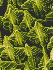
In general, solidification microstructures that are observed in welds are often quite complicated and difficult to interpret. Significant progress has yet to be made in characterizing and understanding the development of microstructures in the FZ. However, at present, attempts are being made to interpret these microstructures by considering the classical ideas of nucleation theory and growth behavior used for conventional solidification processes. During weld pool solidification, unlike in castings or ingot solidification, there is no nucleation barrier and, accordingly, no under cooling of the liquid required for nucleation of the solid. Solidification occurs spontaneously by epitaxial growth from the partially melted grains in the BM. The development of microstructural features during growth of the solid in the FZ is controlled by the shape of the solid/liquid interface. The nature and the stability of the solid/liquid interface is mostly determined by the thermal and constitutional conditions that exist in the immediate vicinity of the solid/liquid interface. Depending on these conditions, growth of the solid will occur by planar growth or by cellular or dendritic modes. If conditions are favorable, a dendrite will exhibit secondary and tertiary arms. Figure 10 shows a scanning electron micrograph of a dendrite in a nickel-based superalloy single-crystal weld. Solidification theories have been developed for interface stability under the conditions of equilibrium at the interface [61, 62] and these theories can be extended to welds.
The morphological stability of the solidification front and the development of microstructures have been discussed elsewhere using the concept of constitutional super cooling [61, 62].
The criterion for constitutional super cooling for plane front stability can be mathematically stated as
(1)
the criterion for plane front instability can be stated as
(2)
Where GL is the temperature gradient in the liquid, R is the solidification front growth rate, ΔΤ0 is the equilibrium solidification temperature range (at composition Co), and DL is the solute diffusion coefficient in liquid.
Although the method of using GR and G/R relations to understand the solidification modes is simple and elegant, modeling of solidification morphology in a typical weld must consider other factors, such as fluid flow and the effect of base-plate texture. The concept of constitutional super cooling is very useful for broadly understanding the development of microstructure and the influence of process parameters on these microstructures in welds.
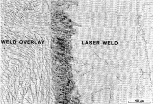
With the increased use of high cooling rate, high energy density welding processes such as electron and laser beam welding, observation of non equilibrium microstructure are becoming very common and are well documented in austenitic stainless steel welds. [63-67]. Figure 11 shows a fully austenitic microstructure in a laser weld which would normally contain a duplex austenite plus ferrite microstructure. The magnitude of such departure from what is the normal microstructure is not very well understood or characterized. Recent advances in rapid solidification theories are being extended to understand the development of non equilibrium microstructures in welds. [68-72] Another significant aspect of weld pool solidification is the solute distribution. During solidification, extensive solute redistribution occurs, resulting in segregation that can drastically affect weldability, microstructure, and properties. Most of the FZ hot-cracking problems associated with a wide variety of common engineering materials is in large part due to elemental segregation during weld pool solidification. Segregation on a fine scale (few micrometers) is called micro segregation; segregation on a large scale (millimeters or greater) is known as macro segregation. It is only recently that some attention is being given to this important aspect of weld pool solidification [73, 74]. In evaluating solute redistribution in welds under dendritic growth conditions, the dendrite tip temperature is extremely important [74]. The tip temperature and composition are strong functions of tip radius, growth rate, thermal gradient, and other factors in welds. Since the structures are finer in welds because of higher growth rates, the contribution to the total under cooling due to the dendrite tip curvature effect is very significant. The consequences of increased dendritic tip under cooling due to the dendritic tip curvature effect are to increases in the dendrite core composition and to reduced micro segregation.
A critical micro structural feature that controls the hot-cracking tendency and properties of welds is the FZ grain structure. Since solidification proceeds spontaneously by epitaxial growth of the partially melted grains in the BM, the FZ grain structure is determined to a large extent by the BM grain structure. Crystallographic effects and welding conditions have been found to significantly influence the development of grain structure [21]. Often the grains during weld pool solidification tend to grow along a crystallographic direction (i.e., the easy growth direction) [21,75]. For cubic metals the easy growth direction is <100>. Conditions for growth are optimal when one of the easy growth directions coincides with the heat flow direction. Therefore, during welding, among the randomly oriented grains in the polycrystalline base metal, the grains that have one of their <100> crystallographic axes most closely aligned with the heat flow direction will be favored. A number of fundamental issues related to the microstructural development of the FZ, such as details of the mechanisms of the grain growth selection process, the role of weld pool shape on the grain or dendrite selection process, grain multiplication or transition, and the related predictive capabilities are currently being addressed. This analysis can be applied to understanding of single crystal welds specifically Ni-based alloys and problem of stray grain formation [76].Recent developments in this area include theoretical and experimental analyses of the dendrite growth selection process and transitions in the grain structure [77].
An extremely powerful experimental technique that utilized macro single crystals of Fe-15Ni-15Cr has been used to investigate the details of the micro structural development [57–59]. The analytical model based on modern solidification theories provides a relationship between travel speed, solidification velocity, and dendrite growth velocity to predict three-dimensional micro structural features in the FZ. Furthermore, from the experimental observations of the dendritic arrangements, a three-dimensional reconstruction of the weld pool is possible. Figure 12 shows reconstruction of weld pool showing the development of weld micro structural features. Finally, significant progress on the beneficial effects of having a fine-equiaxed grain structure in the FZ center is being modeled [77].
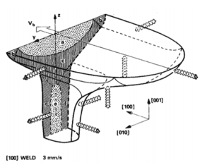
3.1 Phase Transformation
During welding, extensive solid-state phase transformations occur in both the FZ and the HAZ. The nature of these transformations depends on the heating rates, the cooling rates, and the maximum temperature reached at any given location during the weld thermal cycle. Depending on the thermal cycles and temperature gradients that result from welding, phase transformations and grain growth occur, and micro structural and composition gradients and residual stresses develop in the HAZ and FZ. Characterization and modeling of these transformations and the resulting microstructures in weldments remain great challenges. Because of the extensive thermal gradients and non uniform thermal exposure, both the FZ and the HAZ often exhibit significant compositional, micro structural, and property gradients. Such gradients are unique to welded structures. In addition, generation of thermal stresses during welding can drastically affect the kinetics of solid-state transformations in both the FZ and the HAZ. Significant advances have been made in recent years in modeling the solid-state phase transformations in weldments [78-84]. Models have been developed based on physical metallurgy principles. Efforts have been made to use Monte Carlo techniques to simulate grain growth behavior in the HAZ and to quantitively predict micro structural evolution in the HAZ [85, 86]. In most of the alloy systems, the development of microstructure depends on a series of events. In the case of low alloy steels, the sequences of events that occur are shown in Figure 13. The model for microstructure development in low alloy steel has a number of sub models recorded on the sequences of events that the weld metal goes through. In low alloy steel welds, the properties of steel are improved by maximizing the amount of acicular ferrite phase constituent in the microstructure. Although acicular ferrite forms from austenite, the feasibility of acicular ferrite formation depends on the presence of inclusions and austenite grain size.
4.CHARACTERIZATION OF WELD MICROSTRUCTURE
One of the most important developments in welding is the application of advanced characterization tools to probe the microstructure of a weld and to understand the evolution of microstructure in welds. Often weld microstructures are complex with composition, microstructure, and stress gradients. In the past the influence of these factors on microstructure and properties could not be determined because advanced characterization tools were not available at the microscopic and atomic scales. Now with the development of advanced characterization tools such as analytical electron microscopy, atom probe field ion microscopy, and scanning tunneling microscopy, microstructures with gradients can be characterized on an atomic scale. Figure 14shows a three-dimensional map of a simulated HAZ in blast-resistance steel showing nano scale copper precipitates in a marten site matrix [87-89].
Until recently, weld metal characterizations have been done by postmortem analysis. This does not tell us exactly what happens as the weld metal cools from a liquid state to a solid state or during subsequent solid-state reactions that may occur. The same holds true for the HAZ. Recent developments in the application of synchrotron light sources has enabled insitu characterization of welds as they go through the weld thermal cycle and the capture of all the phase-change events that take place during welding [87-90].
Recently, synchrotron diffraction has been used to observe insitu the solidification behavior and other phase transformations in welds [87-89]. For example, in Fe-C-Al-Mn steel under normal conditions, the primary phase to form from the liquid is d-ferrite as observed by time-resolved x-ray diffraction (TRXRD). However, under rapid cooling conditions, the primary phase to come out of the liquid is primary austenite (non equilibrium austenite phase). Figure 15is a representation of TRXRD data that shows the formation of primary austenite during rapid cooling [89,90]. X-ray and neutron diffraction are also finding applications for insitu neutron characterization of weldments [91].
5. RESIDUAL STRESSES AND DISTORTION
One of the consequences of welding is the development of residual stresses and distortion. Residual stress is the stress that exists in a structure even when the external loads are removed. Residual stresses are also known as internal stresses and reaction stresses. During welding, complex thermal and phase transformation stresses are generated by localized heating and spatial variation of heating and cooling. It is well established that, thermal expansion and contraction of the solid during weld thermal cycles in a multi pass weld generate considerable thermal stresses and stress gradients that can exceed the yield strength of the material and may manifest as distortion.
Residual stresses are not unique to welding. They occur in metallurgical processes such as casting, annealing, and phase transformation. Residual stresses can lead to distortion and internal fracturing. They also can degrade the corrosion resistance and reduce the fatigue strength of the material. Residual stresses can be classified into three groups [92]:
- Type I: macro residual stresses that develop on a scale larger than the grain size of the material.
- Type II: micro residual stresses that vary on a scale of individual grains.
- Type III: micro scale residual stresses that exist within a grain as a result of presence of dislocation through crystal defects.
In the last three decades significant advances have been made in our understanding of the origin and influence of residual stresses in structures. Computational models can provide a detailed description of the residual stress distribution in a weldment. Although residual stresses have been studied for many decades, accurate calculation and measurement remain as major issues. A prerequisite for the calculations is the detailed and accurate time-temperature history obtained from numerical calculations. Calculations of distortions, stresses, and strains are computationally intensive, and they take significantly more computer time.
Numerical techniques have been developed for understanding welding-induced residual stress [93-99]. Excellent reviews [100-101]. Address the effect of residual stresses on fatigue life and structural integrity, measurement techniques, and roles in fracturing. Recent advancement of high-performance computational code significantly reduced the computational time for complex three-dimensional welding residual stress simulations that are essential to capture the complex residual stress state of nuclear piping components and automotive body structures. In some cases, the reduction of computational time has been so drastic – a full three-dimensional simulation of a nuclear reactor piping components that would take 18-20 years computational time with today’s commercial FEM codes can be done in 3-4 days with the HPC code on the same computational platform (i.e, over 2000 times increase of computational speed[102-103]). Whereas early computational modeling of weld residual stresses was often limited to thermal-mechanical aspects, recent advancement of integrated computational weld engineering (ICWE) models have resulted full integrations of the thermal-metallurgical-mechanical phenomena that are essential for accurate and reliable prediction of weld residual stresses in highly engineered high-performance materials such as precipitation hardened high-strength aluminum alloys, nickel based superalloys, and high-strength steel in which the micro structural changes in the weld and HAZ region could significantly affect the magnitude and distribution of weld residual stresses [104-105]. Considerable advancement in our ability to predict weld performance such as Type IV cracking in creep resistance ferritic steels are also developed [106].
A number of techniques are available to measure residual stresses. Some are destructive, such as contour methods; semi destructive, such as deep-hole and center-hole drilling; and nondestructive, such as x-ray, synchrotron, and neutron diffraction and magnetic and ultrasonic techniques [100,107-109]
The diffraction-based method is based on elastic strain measurements using Braggs law:
nλ= 2dsin θ (3)
where n = integer, λ = wavelength, d = lattice parameter, and θ = diffraction angle. The stress is calculated using Hook’s law along with elastic constant (E) and Poisson’s ratio (μ). Of the three diffraction-based techniques, only neutrons can give a three-dimensional measurement of residual stress without any damage to the specimen. This is mainly because neutrons can penetrate any engineering materials. For example, it can penetrate 30 mm of steel and 180 to 200 mm of aluminum [110]. Neutrons are also used for in situ characterization of phase transformation [111-112]. The selection of the technique depends on depth of penetration, required resolution, and the nature of specimen.
Residual stresses that develop as a result of welding can cause component distortion and affect structural integrity. To improve the structural performance of the weld, the tensile residual stress located in the weldment must be relieved. There are a number of stress-relief methods (e.g., thermal and mechanical). They include post weld heat treatment, shot peening, and laser peening. However, all the processes are restricted by the geometry of the structure, and they are very expensive. In steels, an alternate approach to reducing the unwanted residual stresses is to lower the martensite start (Ms) temperature and use low-transformation-temperature (LTT) consumables. These alloys contain 0 to 15 wt% nickel 0 to 15 wt% chromium and exhibit lower Ms temperature. This is an in-process residual stress–control method wherein the compressive stress generated by volumetric changes due to martensitic transformation mitigates the tensile residual stresses generated during welding [113]. Residual stresses are best avoided by suppressing the Ms temperature such that the martensitic transformation can continue to compensate for the accumulation of tensile stresses down to room temperature. A number of investigators have shown that by using LTT consumables it is possible to reduce the tensile stresses that develop in the weldment and to induce compressive stress with significant increase in fatigue strength [114-117]. Efforts are under way to use thermodynamic modeling to design filler metals for mitigation of residual stresses in steels [118-120].
6. SENSING CONTROL AND AUTOMATION
In making a manual weld a master welder uses his sensory perceptions (touch, sight, and hearing) to evaluate the process and make the necessary adjustments for corrective measures if required. All these actions must take place in real time. Success depends on intuition, experience, and skill of the welder, and the process is labor-intensive. In the last four decades, significant advances are being made in taking welding from a job shop technology to an automated and computer-oriented technology. For improved quality and productivity, future welding operations will require automated welding systems with adaptive control [121]. The ultimate goal of adaptive control in welding is to make welds with desired quality, performance, and productivity.
The current trend is to use an emerging tool known as intelligent control or intelligent manufacturing. This will enable one to choose a desirable end factor such as microstructure, properties, defect control, or productivity instead of process parameters such as current, voltage, or speed. Intelligent manufacturing is real-time-based optimization through the entire value chain. This involves a solution to a problem with many highly coupled and nonlinear variables in welding.
One of the elements of intelligent control is sensors. The function of a sensor is to provide information to the control systems to determine the necessary changes to the welding process to produce parts with highest integrity. Significant advances are being made in the development of sensors [122-130].The type of sensors currently being developed include sensors based on arc and weld pool characteristics, infrared, acoustic, and ultrasonic methods.
Efforts are also underway to automate the FSW systems [131,132]. A well-understood framework for control and automation is essential to achieve high-quality FSW.
Welding will continue to grow based on both basic and applied scientific principles. More exciting developments of advanced processes, our understanding of physical processes and process control, and automation are yet to come. New processes will be developed as modifications are made to existing heat sources and processes. With the increase in computational power, welding consumables will be developed based on computational thermodynamics and kinetic models. More insitu techniques using synchrotron and neutron scattering will be used instead of postmortem analysis to determine the origin of microstructures and stresses in welds. Advanced sensors will be developed to enable intelligent weld manufacturing. Therefore, the future of welding looks bright.
ACKNOWLEGEMENT
The authors wish to acknowledge Dr. J. Chen (Oak Ridge National Laboratory) for his valuable time and assistance in preparing the manuscript. We would also like to acknowledge Shirin Badlani and Walter Kosinski for preparing the manuscript and the editing, respectively.
REFERENCES
- M. Slaughter, Weld J. 1979, 58, 17.
- E. Jackson, Weld J. 1963, 42, 216.
- Atterberry Jonathan, ‘How welding works.’ How stuff works.com. How stuff works, Inc.
- A. David and J. M. Vitek, International Trends in Welding Research, Conf. Proceedings 1986, 1989, 1992, 1995, 1998, 2001, 2005, 2008, and 2010. ASM International Materials Park, OH.
- Tian, D. McAllister, H. Collins et al. MetTrans A, 2014, 45A, 4470.
- R. Dehoff, W. J. James, M. M. Kirika et al 2015, Mat. Sci and Tech. 2015, 31(8), 881.
- R. Edwards, L. J. Dasilva, A. Sofia, and D. Olivera, Weld Intl, 2016, 175.
- Khastoon and O. Voitenko, Matl Sci Forum, 2017, 906, 127.
- A. David and T. DebRoy, Science, 1992, 251, 497.
- M. Thomas, 1991 Friction stir butt welding Intl Patent application no. PCT/GB92, patent application no. 9125978-8.
- A. Chatterjee, Optics and Laser Technology, 2018, 99, 60.
- A. David, T. DebRoy and J. M. Vitek, MRS Bulletin 1994, 29.
- DebRoy and S. A. David, Rev of Mod Physics, 1995, 67(1), 55.
- Block-Bolten and T. W. Eagar, 1984, MetTrans. B, 75, 461.
- A. A. Khan and T. DebRoy, Met Trans. 1984, 31(5), 641.
- A. Batanov, F. V. Binkin, et al. 1973, Soviet Phys. JETP, 36, 311.
- L. Chan and J. Mazumder, J. Applied Phys. 1987, 62, 4579.
- Mundra and T. DebRoy, Met Trans. B. 1993, 24B, 145.
- J. Knight, AIAA J. 1979, 17,519.
- Kou, “Welding Metallurgy” John Wiley and Sons, NV-61-63, 1987.
- A. David and J. M. Vitek, Intl Mat Rev. 1989, 34 (5), 213.
- Rosenthal, Weld J. 1941, 20(3), 220s.
- Rosenthal, Trans AIME 1946, 68, 849.
- M. Oroper and T. W. Eagar, J. S. Szekely, WeldJ. 1983, 45, 12s.
- M. Oroper and J. Szekely, J. Fluid Mech, 1984, 147, 53.
- L. Chen, J. Mazumder, and M. M. Chen, Met Trans A, 1984,15A, 2175.
- Zacharia, A. H. Eraslan, D. K. Aidum and S. A. David, Met Trans B. 1989, 20(5), 645.
- Zacharia, A. H. Eraslan, and D. K. Aidum, Weld J. 1988, 67(3)
- Paul, T. DebRoy, Met Trans. B, 1988, 19B, 851.
- F. Nippes, L. L. M and W. F. Savage, Weld J. 1949, 28(12), 556s.
- M. Oroper and J. Szekely, J. Fluid Mech, 1984, 147, 53.
- S. Tsai, and T. Eagar, 1984, Intl Conf. on Modeling of Casting and Welding Processes, AIME, N.Y. 317.
- Kou and D. K. Sun, MetTransA. 1985,16, 203.
- Kou and Y. H. Wang, Weld J. 1986, 65, 63s.
- E. Sundel, S. M. Caryea, L. P. Harris, 1986, G. E. Report 86SR DO13.
- Zacharia, A. H. Eraslan, and D. K. Aidum, Weld J. 1986, 67(1), 18s.
- Zacharia, A. H. Eraslan, and D. K. Aidum et al. MetTrans B. 1989, 20, 645.
- Zacharia, S. A. David, and J. M. Vitek et al. Met Trans B. 1991, 22B, 243.
- T. Choo and J. Szekely, Weld J. 1991, 70, 223.
- Zacharia, S. A. David, J. M. Vitek, et.al, Weld J.1989, 68(2), 499s.
- Zacharia, M. A. Bjerta and S. C. Tonorarje, 1993, Intl Conf. on Modeling and Control of Joining Processes, MCIP, Orlando, FL.
- Miller, T. DebRoy, J. App Physics, 1990, 68, 2048.
- Kou, Y. Le, Met Trans A, 1983, 14A, 2243.
- L. Chan, J. Mazumder, and M. M. Chen, Met Trans A, 1984, 15A, 2175.
- Zacharia, S. A. David, and J. M. Vitek et al. MetTrans A. 1989, 20A, 957.
- Zacharia, S. A. David, and J. M. Vitek et al. Proc. of Symposium on the Metals Science and Joining, 1991, Cincinnati, OH, 257.
- Matsunawa, Intl. Trends in Welding Research, 1992, ASM Intl, Materials Park, OH. Eds. S. A. David and J. M. Vitek.
- R. Heiple and J. R. Roper, Weld J. 1982, 61(4), 197s.
- R. Heiple and J. R. Roper, Weld J. 1985, 64(6), 157s.
- Courtesy of Prof.T. DebRoy, Pennsylvania State University, State College, PA.
- H. Hassoum, Fundamentals of Artificial Neural Network, 1995, MILT Press.
- K.D.H. Bhadeshia, Trends in Welding Research, eds. S. A. David and J. M. Vitek, ASM Intl, Materials Park, OH.
- M. Vitek, S. Iskander, E. M Oblow, S. A. David, et.al, Trends in Welding Research, 1999, eds. S. A. David and J. M. Vitek, ASM Intl, Materials Park, OH.
- Sterjovski, D. Nolan, M. R. Carbets, et.al, J. Metals, Processing and Technology, 2015, 70, 536.
- Sterjovski, M. D. Pitman, et.al, J. Metals, Processing and Technology.
- M. Vitek, S. A. David, C. R. Hinman, Weld. J. 2003, 92(1), 10s.
- Rappaz, S. A. David, J. M. Vitek and L. A. Boatner, Met Trans A, 1989, 20A, 7125.
- Rappaz, S. A. David, J. M. Vitek. and L. A. Boatner, Met Trans A, 1990, 1767.
- A. David, J. M. Vitek, M. Rappaz, and L. A. Boatner, Met Trans A, 1990, 1753.
- S. Babu, Intl Met Rev 2009, 54(6), 333.
- C. Flemings, “Solidification Processing,” McGraw Hill, NY, 1974.
- Kurz and D. J. Fisher, “Fundamentals of Solidification”, Trans Tech PublicationAcadermansdorf, Switzerland, 1986.
- A. David and J. M. Vitek, Lasers in Metallurgy, eds. K. Mukerjee and J. Mazumder, AIMS, Warrendale, PA. 1981, 2247.
- M. Vitek, S. A. Dasgupta and S. A. David, Metall Trans. A, 1983, 14A, 1833.
- A. David, J. M. Vitek and T. L. Hebble, Weld J. 1987, 66(1), 289s.
- Katayama and A. Matsunawa, Proc. of ICALEO, 1984, 60.
- W. Elmer, S. M. Allen and T. W. Eagar, Met Trans, 1989, 20A, 217.
- Mehrabian, Int. Met Rev., 1982, 27, 185.
- Trivedi and W. Kurz, Acta Metall, 1986, 34, 1663.
- Kurz, B. Giovanola, and R. Trivedi, Acta. Metall, 1986, 34, 823.
- J. Aziz, J. Appl. Phys. 1982, 53, 1158.
- A. Jackson, G. H. Gilmer and H. J. Leamy, Laser and Electron Beam Processing of Materials, 104, ed. C. W. White and P. S. Peercy, Materials Research Society, Pittsburgh, PA, 1979.
- C. Lippold, W. F. Savage, Modeling of casting and welding processes, eds. H. D. Brody and D. Apelian.
- A. Brooks, M. J. Baskes, and F. A. Greenley, MetTrans A. 1991, 22A.
- A. David and C. T. Liu, Weld J. 1982, 61(5), 157s.
- M. Vitek, Acta Mater. 2005, 53.
- W. Kerr and J. C. V “Metal Source of Welding” Conf. Proceedings, Eds. M. J. Cieslak, J. H. Perepezco, S. King and M. E. Glicksmen, TMS, Warrendale, PA, 1992.
- S. Babu, S. A. David, J. M. Vitek, Intl Symposium on Phase Transformation during Thermomechanical Processing of Steel 1995 August 20-23, Vancouver, Canada.
- E. Easterling, “Mathematical Modeling of Weld Phenomena”, eds. H. Cerjak, K. E. Easterling, Institute of Metals, London, 1993, 183.
- K.D.H. Bhadeshia and L. E. Svensson, “Mathematical Modeling of Weld Phenomenon”, eds. H. Cerjak, K. E. Easterling, 1993, The Institute of Materials, London, 183.
- K.D.H. Bhadeshia, L. E. Svensson, and B. Gretot, Acta Matl, 1985, 33(7), 1271.
- K.D.H. Bhadeshia, “Recent Trends in Welding Science and Tech.” eds. S. A. David and J. M. Vitek, 1990, ASM Intl, Materials Park, OH. 1990, 187.
- F. Watt, L. Coon, M. Bibby, J. Goldak, and C. Henwood, Acta Metall. 1988, 36, 3029.
- Henwood, M. Bibby, J. Goldak and D.M. Watt, Acta Metall, 1988, 36, 3037.
- Chen, B. Radhakrishanan and R. G. Thompson, IntlTrends in Welding Science and Technology, eds. S. A. David and J. M. Vitek, ASM Intl, Materials Park, OH. 1993, 259.
- Radhakrishnan, T. Zacharia, paper submitted to Met Trans A. 1995, 26, 167.
- Yu, J. Cartony, S. S. Babu and J. C. Lippold, Acta Mater, 2010, 58, 5591.
- S. Babu, Proc. Of Royal Society A, 2002, 45(8), 811.
- S. Babu, et al, Acta Mat, 2002, 50(47) 53.
- Elmer, J. Wang, and Reesler, Met Trans A, 1998, 29, 761.
- Woo, Z. Feng, X. L. Wang, and S. A. David, Sci and Tech of Weld J. 2012, 6, 23.
- A. Kandil, J. D. Lord et al. NPL Report no. MATC (A)04.
- Goldak, “Recent Trends in Welding Research” eds. S. A. David and J. M. Vitek, 1990, ASM Intl, Materials Park, OH.
- Tekriwal and J. Mazumder, 1990, Intl Trends in Welding Science and Technology, eds. S. A. David and J. M. Vitek, ASM Intl, Materials Park, OH.
- S. Oddy, J. Goldak, and M. J. McDill, , Intl Trends in Welding Science and Technology, eds. S. A. David and J. M. Vitek, ASM Intl, Materials Park, OH.
- Dong, Sci and Tech of Weld J. 2005, 10(4), 389.
- Dong, Intl J. of Fracture, 2001, 23, 865.
- Feng, Z, Wang, X-L, Hubbard, CR, Spooner, S. (1996) “A FE model for residual stresses in repair welds.” in Residual Stresses in Design, Fabrication, Assessment and Repair. 119-125. ASME.
- Feng, Z, Wang, XL, David, SA, Sklad, PS. (2007) Sci Tech Welding Joining, 12:348-356
- J. Wethers and H.K.D.H. Bhadeshia, Matl Sci and Tech, 2001, 17, 366.
- J. Wethers, TepPrg. In Physics, 2007, 70, 2211.
- Huang H., Chen J., Carlson B., Wang H., Crooker P., Frederick G., Feng Z. Stress and distortion simulation of additive manufacturing process by high performance computing. American Society of Mechanical Engineers. In ASME 2018 Pressure Vessels and Piping Conference (pp. V06AT06A009-V06AT06A009)
- Huang H., Chen J., Carlson B., Wang, H., Crooker, P., Frederick, G., Feng, Z. Prediction of residual stresses in a multipass pipe weld by a novel 3D finite element approach. American Society of Mechanical Engineers. In ASME 2018 Pressure Vessels and Piping Conference (Paper No. PVP2018-85044, pp. V06BT06A084).
- Feng, Z. (2016) “Application of ICME to Weld Process Innovations and Residual Stress Management (Keynote).” in 10th Int Conf on Trends in Welding Research. Tokyo, Japan.
- Feng, Z, Wang, XL, David, SA, Sklad, PS. (2007) Modelling of residual stresses and property distributions in friction stir welds of aluminum alloy 6061-T6. Sci Tech Welding Joining, 12:348-356
- Feng, W. Zhang, Y Wang, Y Wang, Y. Gao, “weldability of creep-resistance alloys for advanced fossil power plants” in Project Review Meeting for Crosscutting Research Portfolios, April 10-12, 2019, National Energy Technology Laboratory, US Department of Energy. https://www.netl.doe.gov/sites/default/files/2019-05/2019_Annual_Reports/Thursday/MaterialsDirectPowerExtractions/4%202019FEAA118_ORNL%20Feng%20Annual%20Review%20v5%20short.pdf
- Payzant, S. Spooner, LX. Zhu, et al. ASME, 1996 Meeting on Pressure Vessels and Piping.
- Wang, X-L, Spooner, S, Hubbard, CR, Maziasz, PJ, Goodwin, GM, Feng, Z, Zacharia, T. (1994) “Residual Stress Distribution in FeAl Weld Overlay on Steel.” in Mat Res Soc Symp. 109-114.
- Wang, X-L, Feng, Z, David, SA, Spooner, S, Hubbard, CR. (2000) “Neutron Diffraction Study of Residual Stresses in Friciton Stir Welds.” in The Sixth International Conference on Residual Stresses. 1408-1414.
- C. Rippley, Materials forum, 30, 2006.
- X-li Wang, Z. Feng, S. A. David, et al. Proc. of the 6th Conference on Residual Stress.
- Zhen Yu, Z. Feng, et al. JOAM 2018.
- K. C. Jones and P. J. Alberry,Metals Tech, 1977, 557.
- Ohita, N. Suzuki, Y. Maeda, K. Hiyaoka, and J. Sasuka, Intl. J. ?1999, 21, S113.
- Ohita, Welding in the World, 1999, 43, 38.
- Ohita, Weld J. 2003, 82, 72.
- Joseph A. Ronevich, Eun Ju Song, Zhili Feng, Yanli Wang, Christopher D’Elia, Michael R. Hill (2019), Evaluating the fatigue crack growth rates of multiple X100 pipeline welds and heat affected zones in high pressure hydrogen gas while considering the influence of residual stress, Engineering Fracture Mechanics, in press.
- A. Francis, and J. Stone, et al. J. Pres.VS Tech. 2009, 131.
- J. Moat and J. Jones et al. Sci & Tech of Welding and Join. 2011, 16(3), 279.
- Feng, X. Yu, J. Bunn, A. Payzant, D. Tzelepis, (2016) “Control of hydrogen embrittlement in high strength steel using specia designed welding wire”, in ShipTech 2016, March 1-2, 2016, Charleston, SC
- E. Cook, K. Andersen and R. J. Barrette, 1990, Trends in Welding Research, eds. S. A. David and J. M. Vitek, ASM Intl, Materials Park, OH.
- Hu, G. Ouden, 1999, Trends in Welding Research, eds. S. A. David and J. M. Vitek, ASM Intl, Materials Park, OH.
- M. Zhang, and L. Li, 1999, Trends in Welding Research, eds. S. A. David and J. M. Vitek, ASM Intl, Materials Park, OH.
- W. Richardson, D. A. Gutow, R. A. Anderson, et.alWeld J. 1984, 63(3), 43.
- Bolstad, 1987, Proc. Of Edison Welding Institute, EWI, Columbus, OH.
- Bolikel and J. Mazumder, 1992, 3rd International Conf. on Trends in Welding Research, eds. S. A. David and J. M. Vitek, ASM Intl, Materials Park, OH.
- Nagarajan, P. Banerjee, W. H. Chen, et al, 1991, IEEE Trans. Robot. Autom, 8(1), 86.
- Dilthey, J. Gollinick, 1999, Proc. of Trends in Welding Research, eds. S. A. David and J. M. Vitek, ASM Intl, Materials Park, OH.
- Chen, Z. Feng, et al. 2016, IEEE Intl Conf. on Advanced Intelligence Mechatronics, IEEE Banff, Alberta, Canada.
- E. Cook, H. Smartt, J. Mitchell, et al, 2003, Weld J. 28.
- E. Cook, R. Crawford, et.al. Weld J. 2007, 53.
C. Smith, 2007, Friction Stir Welding Processes.


